[Technical Lecture Hall] At present, equip with hydraulic power.Automatic transmission (hereinafter referred to as AT)The proportion of models is getting bigger and bigger, compared withManual transmission (hereinafter referred to as MT)Model, its convenience is very prominent. In this article and subsequent articles, the editor will take you to interpret all kinds of knowledge of AT in detail, and as the basic part of the beginning, let’s talk about the basic structure and working principle of AT first.
Usually, we call it AT’s automatic transmission. Its core components are:, planetary gear set,/brake and its control mechanism (solenoid valve, oil circuit), and its peripheral equipment is the transmission housing, etc. Let’s start with the hydraulic torque converter in the order of power flow.
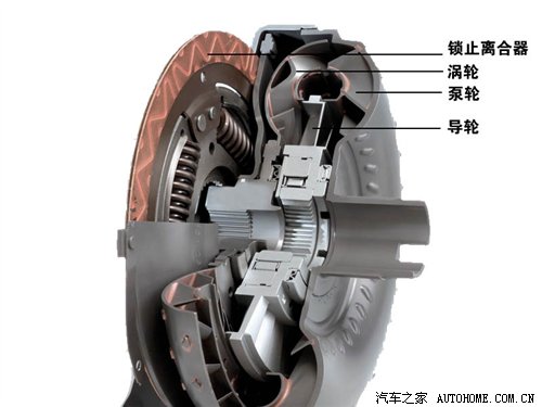
● Hydraulic torque converter
There was a saying that the torque converter on AT was equivalent to the clutch on MT, which played the role of connecting and interrupting power. Actually, this statement is wrong.AT and are directly connected, unlike MT, which has a power switch: clutch. Therefore, from the moment of ignition, the torque converter starts to rotate, and the connection and interruption of power is still completed by the clutch inside the gearbox. The only similarity between the torque converter and the MT clutch, that is, the "soft connection" characteristic of the torque converter, is similar to the "semi-linkage" working condition of the MT clutch.
The working principle of hydraulic torque converter is like two fans facing each other. One fan works and then blows the other fan that doesn’t work. This metaphor can vividly explain the working relationship between the pump wheel and the turbine in the hydraulic torque converter. However, explaining its working principle in detail is somewhat complicated.

After power output, the pump wheel connected with the torque converter housing is driven, and the pump wheel stirs the torque converter.Oil (hereinafter referred to as ATF), driving the turbine to rotate, ATF is a circular action in the shell. Due to the centrifugal force when the pump wheel rotates, ATF will be thrown to the outside under the action of the pump wheel, rushing to the turbine in front, then flowing to the axial position and returning to the side of the pump wheel. This cycle will transmit power to the turbine connected to the gearbox.
However, only this component and transmission mode can only be called hydraulic coupler. If you want to become a hydraulic torque converter, you must change the shape of turbine blades. In this way, when ATF is recycled back to the pump wheel through the turbine, it will rotate in the opposite direction to the pump wheel, thus causing impact. Therefore, in order to become a hydraulic torque converter, you need another component: the guide wheel. The guide wheel is a component between the pump wheel and the turbine, which is used to adjust the direction of ATF liquid flow in the housing and is fixed to the housing through a one-way clutch.
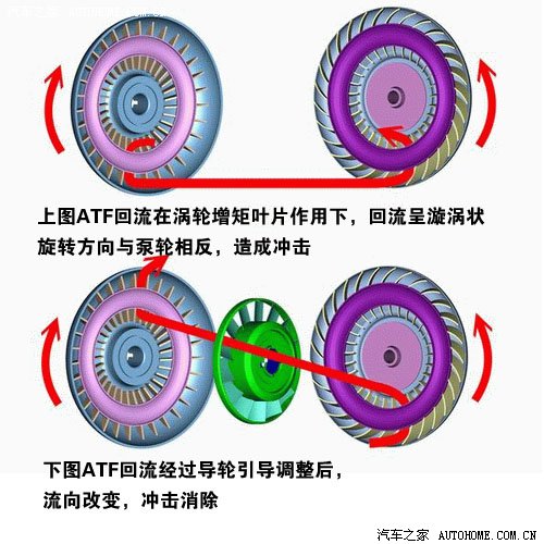
With the guide wheel, there is the soul of "torque change". When the speed difference between the pump wheel and the turbine is large, the power output is also large. At this time, the torque converter wants to be a continuously variable transmission, through the speed difference.Raise the torque, and the guide wheel is in a fixed state at this time., used to adjust ATF reflux; However, when the speed difference is reduced and the turbine impeller is coupled or locked, the torque is close to equivalence.There is no need to increase the torque, and the guide wheel rotates in the same direction as the pump wheel and the turbine.Avoid stirring ATF by yourself, resulting in power loss.
At this point, we have learned the biggest feature of hydraulic torque converter-soft connection, and this power transmission mode has played two major functions: 1. A smooth start from standstill to low speed; 2. In the acceleration process, when the power output is large, it can increase the torque. If compared with the clutch on MT, it should be noted that the first one has played and optimized the function of the clutch on MT, but the second one cannot be realized by the clutch.
However, the inherent "soft connection" feature of hydraulic torque converter has a weakness. The power is not directly output, and the rotation speed of the pump wheel is higher than that of the turbine when the torque output is equivalent. In this case, when transmitting power, ATF still circulates in the shell, wasting power. Therefore, almost all hydraulic torque converters have an efficient and energy-saving component: the hydraulic torque converter lock. The locking device is in the form of a multi-disc clutch, and its function is to lock the pump wheel and the turbine when the torque converter is in a coupled state and there is no need to increase the torque. In this case, the power transmission is a "hard connection", and all the lossless (or a little power loss) will be transmitted from the crankshaft to the next station: the gearbox.
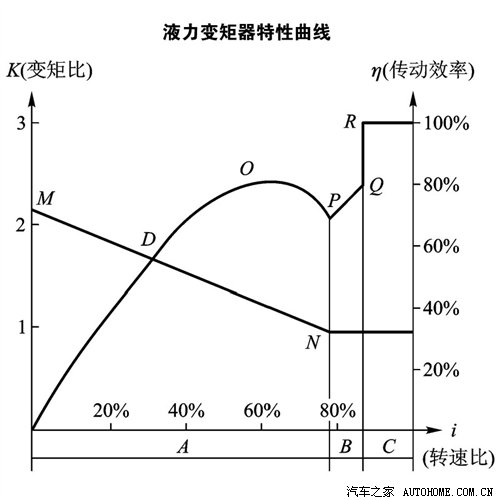
Simply explain the above picture: the I-axis is the speed ratio, indicating the ratio of the speed of the turbine and the pump wheel. The speed of the pump wheel at the left end is much greater than that of the turbine, and the right side is equal. When starting or stepping on the accelerator with big feet, the rotation speed is relatively small, and the pump wheel is much faster than the turbine. At this time, the output torque of the pump wheel is much larger than the input torque of the turbine, which is more powerful, but the transmission efficiency is lower; When stepping on the accelerator lightly, the speed ratio increases, the torque ratio decreases, and the transmission efficiency increases accordingly. When the speed ratio is 60%, the efficiency is the highest. When the throttle is stabilized and the speed is relatively stable, the speed ratio further increases and the torque ratio is close to 1, but the transmission efficiency decreases at this time; In order to avoid power loss, the torque converter is locked with the clutch, and the speed ratio suddenly increases to 1, and the efficiency also reaches the highest.
● Hydraulic torque converter is not a feature of AT.
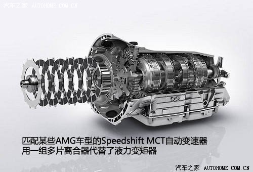
Hydraulic torque converter is not unique to AT, and some transmissions also use hydraulic torque converter as the mechanism to optimize power. AT does not absolutely use hydraulic torque converter to realize soft connection. For example, the Speedshift MCT automatic transmission used on some AMG models replaces the hydraulic torque converter with a pair of multi-disc clutches. Therefore, the hydraulic torque converter is not the biggest feature of AT, but the planetary gear set working in cooperation with multiple clutches/brakes is the biggest feature of automatic transmission.
● Planetary gears and planetary gear sets in AT gearbox
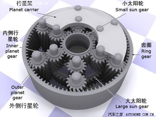
On MT, each gear has a set of two normally meshed gear pairs, and only the output shaft needs to be splined with the output gear of that gear to change gears. In AT, not so many gears are working, but a very unique way to complete the transformation: planetary gear sets. Let’s take a look at the characteristics of a basic ternary planetary gear:
"planetary gear set model"
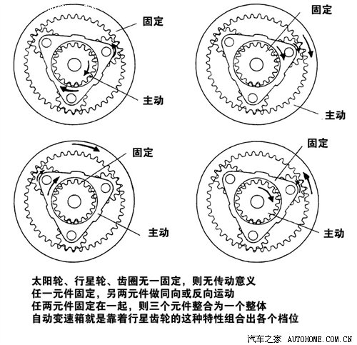
The biggest characteristic of planetary gears is that after different input and output wheels are combined, the tooth ratio and the relative direction of input and output will change, which is very suitable for automobile transmission. In order to increase the gear, the planetary gears on the car are upgraded to gear sets and gear rows, and then the gear shift can be completed through a series of actuators.
● AT actuator: clutch, one-way clutch and brake.
As we have learned above, what kind of transformation forms a group of planetary gears has, and the components responsible for transformation and input and output are a series of actuators: clutches, one-way clutches and brakes. With these actuators, planetary gears can be combined in different ways to match different power flows and have different transmission ratios. These operations are controlled by the matching oil pump, slide valve, hydraulic pressure and complex hydraulic circuit.
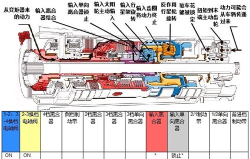
"The picture shows the position and working conditions of each component of the old 4T65E automatic transmission when it is in neutral."
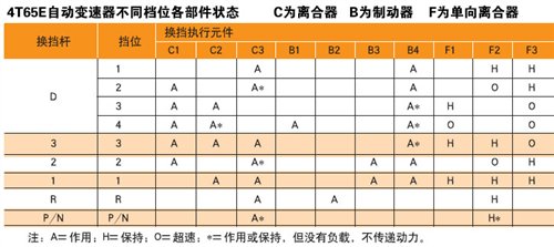
Different gears are formed under different combinations of multiple actuators and planetary gears.
At this point, the power from the engine has been reorganized, and the ever-changing torque and speed are transmitted to the wheels. Compared with MT, the convenience is improved, while the internal structure and working conditions are much more complicated. The structure and principle of AT have been introduced. In the next article, the usage of PRND gear on AT is mainly introduced. (Text/car home Ren Fei)
Related links:
